|
Many years ago I started work on translating a poorly written paper on a really good shadow mapping technique for publication in Game Engine Gems. I never finished the paper, but the technique is used in production in Firefall. Of all the shadow mapping techniques I've tried, its the best for Firefall's use case. Rather than wait for perfection, I figured I'd just post it in case somebody finds it useful. 
1 Comment
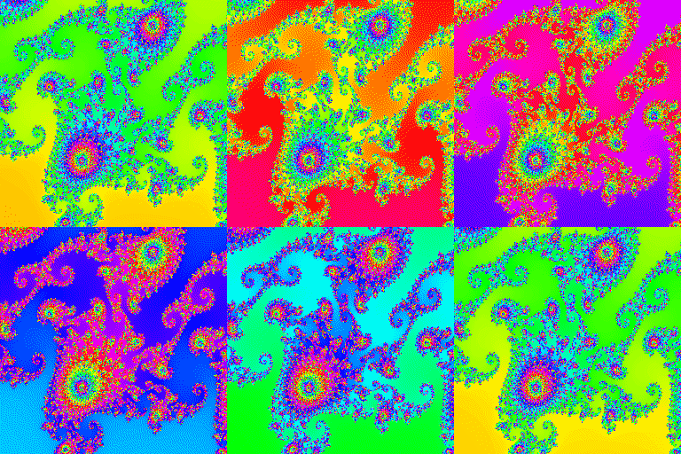
Basic Usage: // 4 component. RGBX format, where X is unused char *frame = new char[128*128*4]; jo_gif_t gif = jo_gif_start("foo.gif", 128, 128, 0, 32); jo_gif_frame(&gif, frame, 4, false); // frame 1 jo_gif_frame(&gif, frame, 4, false); // frame 2 jo_gif_frame(&gif, frame, 4, false); // frame 3, ... jo_gif_end(&gif); Where frame holds the RGBA pixels for a frame. You call start, then frame a bunch of times then end. Here is a more interesting example used to create the image above. :) Enjoy!
void hsv2rgb(float hsv[3], float rgb[3]) { if(hsv[1] <= 0.0) { // < is bogus, just shuts up warnings rgb[0] = rgb[1] = rgb[2] = hsv[2]; return; } float hh = hsv[0]; if(hh >= 360) { hh = 0; } hh /= 60; long i = (long)hh; float ff = hh - i; float p = hsv[2] * (1.f - hsv[1]); float q = hsv[2] * (1.f - (hsv[1] * ff)); float t = hsv[2] * (1.f - (hsv[1] * (1.f - ff))); switch(i) { case 0: rgb[0] = hsv[2]; rgb[1] = t; rgb[2] = p; break; case 1: rgb[0] = q; rgb[1] = hsv[2]; rgb[2] = p; break; case 2: rgb[0] = p; rgb[1] = hsv[2]; rgb[2] = t; break; case 3: rgb[0] = p; rgb[1] = q; rgb[2] = hsv[2]; break; case 4: rgb[0] = t; rgb[1] = p; rgb[2] = hsv[2]; break; case 5: rgb[0] = hsv[2]; rgb[1] = p; rgb[2] = q; break; } } int main(int argc, char **argv) { const int w = 256, h = 256; jo_gif_t gif = jo_gif_start("foo.gif", w,h,0,32); for(int frame = 0; frame < 360/4; ++frame) { unsigned char tmp[w*h*4]; double coordX = -0.74529; double coordY = 0.113075; double zoom = 1.5E-4*0.5; for(int y = 0; y < h; ++y) { for(int x = 0; x < w; ++x) { double x0 = (x/double(w) * 3.5 - 2.5) * zoom + coordX; double y0 = (y/double(h) * 3.0 - 1.5) * zoom + coordY; double xx = 0, yy = 0; int iter = 0; while(xx*xx + yy*yy < 2*2 && iter++ < 4096) { double xtmp = xx*xx - yy*yy + x0; yy = 2*xx*yy + y0; xx = xtmp; } int i = y*w*4+x*4; int iter2 = iter + 360 - frame*4; float hsv[3] = { float(iter2%360), 1, iter2 < 4096 ? 1.f : 0.f }; float rgb[3]; hsv2rgb(hsv, rgb); tmp[i+0] = (unsigned char)(rgb[0] * 255); tmp[i+1] = (unsigned char)(rgb[1] * 255); tmp[i+2] = (unsigned char)(rgb[2] * 255); tmp[i+3] = 255; } } jo_gif_frame(&gif, tmp, 4, false); } jo_gif_end(&gif); } The crescent bay demo was very good. The headset was light, latency was fantastic, the picture was solid and sharp taking very good advantage of low persistence, the content was beautifully rendered and very enjoyable. All told a very solid improvement over dk2. The valve demo was better and it's hard to explain why. Their tracking was just as good, their latency and/or persistence was *slightly* worse, I *think* the headset was heavier ( I didn't have both at the same time to directly compare ), they had no hrtf audio - so it wasn't technically a win but still it was better for some reason... Why? I think for a few reasons. One is that the walkable area is 5 times bigger than what oculus demoed increasing immersion immensely, second is they had perfectly tracked controllers which provided a way for you to interact with the virtual world in a very fun and personal way, and third ( and most important ) is that the content they showed was amazingly fun and really showed off the walkable area and controller interaction. The first demo was a small controller introduction where you would press the right trigger and a balloon would blow up out of your hand and float away. It was physically simulated so that you could then interact with the balloon with the controllers. At one point I tried to catch the balloon by instinctively pressing it against myself, but it went right through me ( which was a very weird sensation ). this demo was so incredibly fun. The second demo iirc was where I was on a bridge of a sunken ship under the ocean. Lots of creatures swam by including a giant whale. Very peaceful. Next I think was the VR painting demo which showed a really cool 3d interface and some pretty awesome painting. Very beautiful and very fun! Another demo of a tabletop game where miniature people were fighting each other. Pretty cool, but nothing to write home about there. Though I can see a cool game being made with this kind of setup. There was a surgeon simulator demo which was pretty darn awesome :) you are in space with an alien on the table and another table with various tools on it. Your controllers turned into hands which you could open and close very similarly to a prosthetic hand. It was a little awkward, but I laughed and had a lot of fun doin surgery then taking alien organs and stuffing them into the aliens mouth. Lol There was another demo where you would walk around and depending on where you walked the room would change to a different room. I think this game was there to show off a kind of transportation travel method. It was fun, but a bit confusing. Last demo was an aperture science demo where they had you open drawers pull levers and try to fix a broken robot. Was lots of fun. Then finally the walls were torn away to find yourself in a shipping crate. A giant robot came by. The floor started to tear away. Was just fantastic. That's the end of the demos and then something funny happened that I can't fully explain. When the headset came off, I had a very primal need to get back into VR. I didn't *want* to get back into VR, I *needed* to. Something was compelling me. I noticed it right away as foreign and was a bit confused about how a VR experience can ilicit a drug like response. I spend a lot of time in VR, so this is very unusual. I think the primary cause is the content difference, but I can't be sure. I have been told I am not the only one, and that is kinda cool and also kinda scary. It means awesome things if you are a VR dev as it means VR will spread like an unstoppable virus. They will not be able to make VR headsets fast enough to meet demand - not by a long shot. The down side is that there are some possibly serious and negative societal side effects of VR. That is beyond what I already worried about before it was addictive. We may see some government regulation of VR. All told though as a VR dev myself, I'm super excited and impressed that VR has come this far in such short a time. One thing is clear, the future is virtual. Welcome to part 4 of the DXT compression series. In this series I go over the techniques and results used to compress Firefall's texture data as they are uncovered and implemented.
In this post I go over a lossy algorithm reducing the data size on disk - Or how I went from 2.5bpp to 1.5bpp with very little visible and measurable loss in quality. Previous posts on this topic: Part 1 - Intro Part 2 - The Basics Part 3 - Transposes In Part 2 we determined the baseline of optimized LZMA compression on DXT5 data, which is 2.28bpp on average for my test data set from Orbital Comm Tower in Firefall. In Part 3, we went over various transposes of data and found that they only make a small impact to 2.25bpp. Alright, here we go! Welcome to part 3 of the DXT compression series. In this series I go over the techniques and results used to compress Firefall's texture data as they are uncovered and implemented.
In this post I go over some simple data transpose options with some rather non-intuitive results. Previous posts on this topic: Part 1 - Intro Part 2 - The Basics Part 4 - Entropy In the last post we determined the baseline of straight up LZMA compression on DXT5 data, which is 2.28bpp on average for my test data set from Orbital Comm Tower in Firefall. Welcome to part 2 of the DXT compression series. In this series I go over the techniques and results used to compress Firefall's texture data as they are discovered and implemented. Red 5 Studios has graciously allowed me to post about this work publicly with the intention that peer review and group process will end up with something better overall, not only just for Red 5 but for others in the industry as well. So please do comment and suggest improvements if you have ideas or thoughts on the matter :)
Today I've been researching various DXT compression algorithms that attempt to reduce the on disk footprint of DXT textures. I have a loose requirement though that it has to be lossless. The reason is we already have blocking artifacts due to DXT and I don't want to make them worse. The exception of course is if it really is absolutely not noticeable, even to an artist.
I love it when you can cut through pages of format specification to deliver something simple. To that end I added another minimalistic code gem - WAV file writing in a single function. It only supports PCM format, but its amazingly handy when you need it! :) If you want to see DPCM format support post in the comments or send me an email.
Among other things, I've also been hard at work in my off time on a single file, minimalistic MPEG file writer. |
Archives
November 2021
Categories |
||||||

 RSS Feed